A molded part develops a step at the parting line. Maintenance finds a worn alignment lock, measures its outside dimensions and orders a replacement. The new component fits the pocket—but the mismatch remains, or the mold now closes more tightly than before. What went wrong?
This is an illustrative purchasing problem, not a reported customer case. It exposes a common gap in a replacement specification: fitting the mounting pocket is not the same as restoring the relationship between the mold halves. That relationship also depends on the mating component, the pocket’s location, the engagement sequence and the operating condition.
Quick answer: Leader pins and bushings guide the mold halves during opening and closing. Dedicated mold interlocks provide additional registration where the design requires it. They are complementary functions, not automatically interchangeable solutions. Before ordering a replacement, identify the exact system, inspect the mating part and locating pocket, and define how alignment will be accepted in the assembled mold.
This guide concerns injection-mold alignment components. Here, interlock means a mechanical locating device—not a safety interlock, ejector return system or slide-actuation mechanism. Installation and closing checks should be performed by qualified personnel under the mold and machine’s approved procedures.
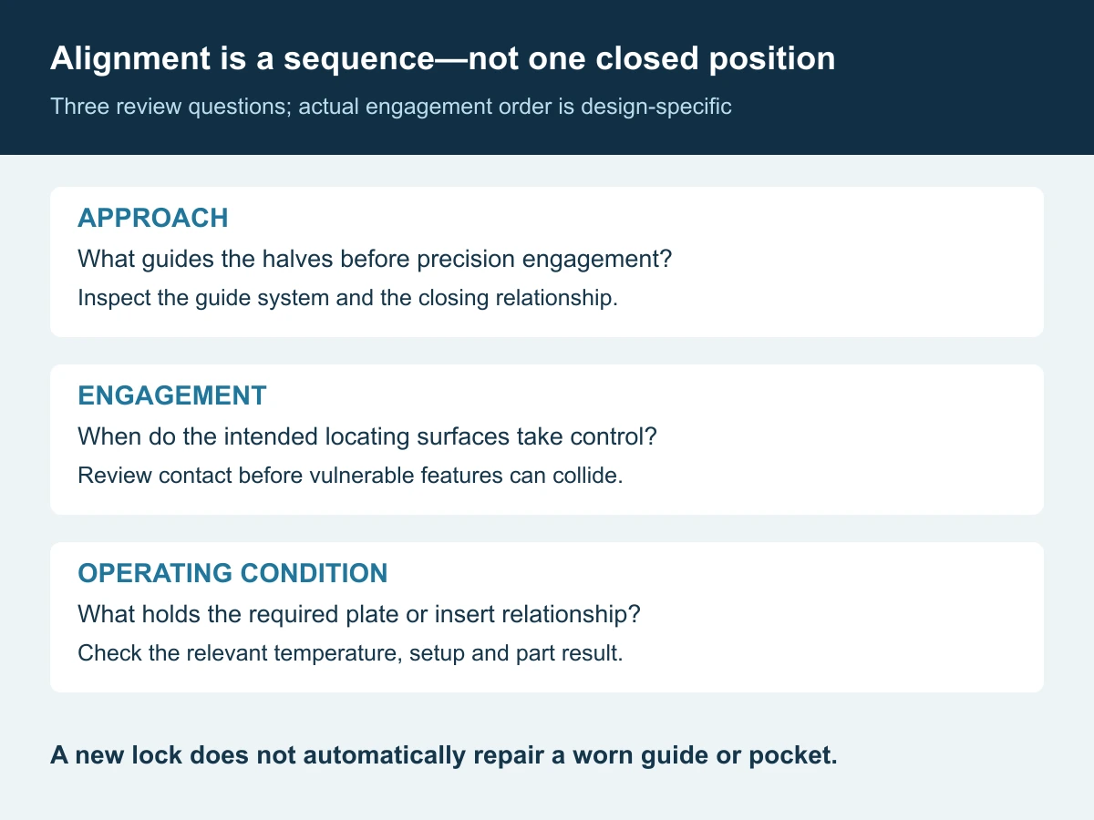
1. Start with the alignment function, not the component name
“Guide pin,” “leader pin,” “taper lock,” “side lock” and “cavity interlock” do not describe one universal mechanism. Identify which plates or inserts the component locates, which directions it constrains and when its working surfaces engage.
DME’s alignment overview lists leader pins, bushings, taper locks, wedge locks and dowel pins as different options. It identifies part accuracy, resin and processing temperature, mold size and mold design among the selection considerations.[1] The useful purchasing distinction is therefore functional, not simply “ordinary pin” versus “more accurate lock.”
| Function to identify | Question for the drawing review | Evidence to request |
|---|---|---|
| Guidance during approach | What controls the relative position before the precision locating features engage? | Guide arrangement, mating condition and relevant assembly views |
| Registration at the working interface | Which component locates which plate or insert, in which direction? | Datums, locating surfaces and the intended contact or clearance |
| Protection of sensitive features | Is useful alignment established before vulnerable core or shutoff surfaces can collide? | A reviewed closing sequence and critical engagement positions |
| Behavior under operating conditions | Does the accepted relationship persist at the intended temperature and molding setup? | Assembly checks and identified part samples under recorded conditions |
Do not ask a new interlock to conceal an unresolved guide, pocket or mounting problem. A component that repeatedly receives unintended side contact may show wear first without being the original cause. Equally, a sound guide system does not prove that every cavity insert is correctly located within its plate.
2. Diagnose the pattern before deciding what to replace
Map the defect to the mold: cavity number, feature, direction and time in the run. The following comparisons help choose the next inspection; they are diagnostic clues, not proof of a cause.
- Similar mismatch across several cavities: investigate common references and plate-to-plate relationships before assuming several independent inserts failed.
- One cavity differs while the others remain consistent: examine that cavity’s insert seating, local locating features and wear history as well as the common alignment system.
- The condition changes as the mold warms: record the actual thermal condition and consider differential movement. A cold assembly check alone is incomplete evidence.
- Witness marks appear during approach: examine when contact begins. Correct final location does not establish that the closing path is unobstructed.
Separate a geometrical step or mismatch from thin flash, a cosmetic witness line and deformation of the molded part. They can coexist, but they are not the same acceptance characteristic. Marked samples and a measurement method are more useful than an unqualified report that “the parting line is bad.”
If the relationship between the symptom and the alignment system is still uncertain, order an investigation or a dimensional review—not an unqualified promise that replacing a lock will eliminate the defect.
3. Treat temperature as part of the alignment requirement
A mold checked on a bench and a mold running with different temperatures in its two halves are not necessarily in the same geometrical condition. The purchasing specification should state the intended operating conditions and identify any deliberate freedom for expansion.
DME explains that its rectangular tapered interlocks can accommodate plate growth in a direction determined by their orientation. Its FAQ contrasts this with round tapered interlocks, which offer less accommodation for differential expansion, and recommends attention to placement. These are design-specific principles, not permission to substitute one shape for another without reviewing the mold.[2]
The important distinction is between unwanted locating clearance and intentional movement in a non-locating direction. Removing the latter in pursuit of a “tighter fit” can make independently expanding features constrain each other. Conversely, excessive play in the direction that must locate the cavity is not a thermal-expansion strategy.
Ask the designer to mark the constrained and relieved directions on an assembly view. Record the relevant plate or insert temperatures when accepting the mold; controller setpoints alone do not establish that all steel has reached those temperatures. Do not prescribe a universal gap, preload or thermal offset without the particular material, geometry and operating conditions.
4. Specify the locating surfaces—not just the outer envelope
Outside size and screw spacing help identify a component. They do not fully define how it works. For a custom replacement, identify the relationship between the mounting references and the working locating surfaces, including any surfaces that must remain clear.
DME’s catalog specifies taper seating, rather than male-to-female face contact, for the round tapered interlocks described in its installation section. Separate pages describe independent replacement for Black & Gold side/top interlock components.[3] Neither statement should be generalized to every product called a mold lock.
A replacement can therefore be wrong even when its mounting holes line up. Examples include a shifted working surface relative to the mounting datum, a different engagement height, an unapproved face contact or a worn pocket that no longer locates the part as intended. A tighter manufacturing tolerance on the replacement will not correct the wrong nominal relationship.
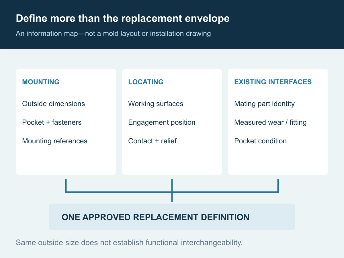
For a worn sample, distinguish measured as received from intended new-part geometry. Copying wear into a new part can preserve the very error the replacement was meant to remove. Identify previous grinding, shimming or local fitting before releasing a drawing.
For a drawing-specific locating detail, HC Precision can review the component’s mounting faces and contact geometry together with its machining and inspection requirements. CNC, EDM or grinding is selected around the features that need to be controlled. This is particularly useful when a replacement has to work with retained tooling: the quotation can distinguish the new part’s measurable requirements from checks that still require the actual mold assembly.
5. “Available individually” does not mean “compatible with anything”
There is no sound universal rule that every interlock must be replaced as a pair—or that replacing only the visibly worn half is always acceptable. The decision depends on the exact product family, its replacement rules and the condition of the retained component.
A concrete example shows why the series matters: Progressive Components’ catalog says its counterbored-style taper locks are supplied as assemblies and must not be combined with the threaded-style taper locks on the following catalog page.[4] This is a specific prohibition on mixing those styles; it is not evidence that every taper lock is a uniquely matched pair.
| Purchase condition | Practical decision |
|---|---|
| Exact manufacturer and series identified; individual replacement is permitted; retained mate and pocket meet requirements | Consider replacing the specified half, followed by the required assembly checks. |
| Series, dimensional revision or previous fitting is unknown | Establish the interface definition before committing to a single-part replacement. |
| Both working surfaces are damaged, or the retained mate fails inspection | Evaluate a compatible set and investigate the damage mechanism; replacing only one half leaves the other defect. |
| Mounting pocket or its locating reference is damaged | Define the pocket repair and new-part relationship together. A new set alone may not restore location. |
| A custom alternative is proposed for a catalog component | Review mating geometry, engagement, materials and surface condition explicitly. Similar appearance is not interchangeability evidence. |
Do not infer compatibility across brands from a shared nominal size. Also avoid treating hardness or coating color as a complete specification: the mating material and surface-treatment combination belongs to the design, not to a blanket “harder is better” purchasing rule.
6. Give the supplier an RFQ that can be accepted objectively
The most valuable RFQ attachment is often an annotated assembly view, not another photograph of the loose part. Use the following compact package to separate the supplier’s component responsibility from the toolmaker’s assembly responsibility.
- Identify the system. Include mold ID, location, component manufacturer and series if known, quantity, drawing revision and whether the order is for one half or a set.
- Define the interfaces. Provide mounting datums, pocket information, mating geometry, working surfaces and the intended fit. Distinguish nominal dimensions from wear measurements.
- Describe the problem. Supply marked photographs, affected cavity numbers, sample measurements and relevant maintenance or fitting history.
- State the working condition. Identify the relevant temperature range, unusual temperature differences and the closing or engagement requirements that affect the detail.
- Define delivery and inspection. State material and surface condition, required inspection characteristics, any fitting allowance, and whether supply is component-only or includes separately agreed assembly work.
- Assign release responsibility. Name who checks the installed relationship and who approves the molded-part samples. Agree the measurement conditions and acceptance limits before manufacture.
A useful acceptance statement identifies the feature, direction, datum, limit and condition of measurement. “No mismatch” without a defined location or method is not an adequate replacement specification. A component inspection report supports the part’s conformity; it does not alone demonstrate alignment of the complete production mold.
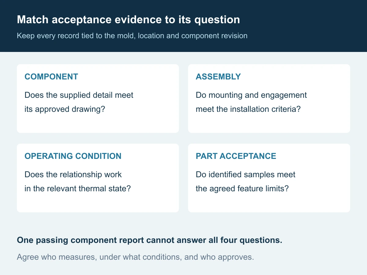
Request the replacement around its mating interfaces. HC Precision manufactures custom precision mold components to customer drawings and can help prepare a drawing when the definition is incomplete. Send both sides of the locating relationship, mounting details and the observed mismatch. We can review the required component and inspection scope before quotation. Confirm any assembly fitting separately; compatibility with a named catalog interlock must be established for that specific system.
The purchasing insight: a successful replacement restores a defined relationship in the mold. Buy against that relationship—not merely a component that fits the same hole.
Frequently asked questions
Can mold interlocks replace worn leader pins and bushings?
Not as an assumed shortcut. First establish the required guidance and engagement sequence. Adding or replacing a final locating device does not automatically correct approach misalignment or a damaged guide system.
Should I replace the male and female interlock together?
Follow the exact series’ rules and inspect the retained interfaces. Some systems allow independent replacement; unknown or damaged mates require further review. Being sold in sets does not by itself prove that every set is uniquely matched.
Is a tighter interlock always more accurate?
No. The intended locating fit must coexist with the design’s permitted movement and operating temperature. Arbitrarily removing clearance can change engagement or create unwanted constraint.
Does a successful cold closing check prove production alignment?
It establishes evidence for that checked condition. Where operating temperature, loading or local insert behavior matters, verify those conditions and the relevant molded-part results separately.
References and scope notes
- DME — Mold Alignment. Alignment-system options and application factors. ↩
- DME — Interlocks FAQ. Orientation and differential thermal expansion for its round and rectangular tapered interlocks. ↩
- DME — Mold Interlocks catalog. Page 13 explains round tapered-interlock seating; pages 17 and 20 describe Black & Gold individual replacement. Confirm the applicable series and installation information for an actual order. ↩
- Progressive Components — Alignment Locks catalog, C-18. Counterbored-style taper-lock application note; do not generalize its cross-style restriction to other product families. ↩
The diagnostic comparisons, RFQ structure and illustrations are editorial engineering synthesis, not measured customer results or installation instructions. Manufacturer examples explain specification boundaries; they do not imply that HC Precision distributes, duplicates or guarantees compatibility with those products.