A blind threaded hole is not fully specified by its thread size and a single depth. The finished part must provide enough usable thread for the joint, space for the selected screw without unwanted bottom contact, and enough material below and around the hole. Those are different requirements—and making the hole deeper does not automatically solve all three.
For buyers of precision machined parts, this distinction matters before comparing quotations. Two suppliers can read an ambiguous depth note differently, quote different operations and deliver parts that look alike but behave differently in assembly.
HC Precision manufactures drawing-specific precision parts, including custom machined components, mold inserts, cores and punches. We work to customer drawings and can also help prepare them, so your inquiry can start with either a released design or clearly identified questions about the part.
Scope: straight internal fastening threads in machined components. Tapered pipe threads, sealing threads, threaded inserts and safety-critical joint qualification require their own requirements. Numerical values below are hypothetical, not recommended dimensions or HC Precision capability claims.
Separate the threaded region from the drilled cavity
The most useful starting point is a section view. Identify where the complete thread begins, where it ends, where the full-diameter drilled portion ends and where the deepest point lies. An entry chamfer, counterbore or spotface can put these features below the outer surface.
| Requirement | What it describes | What it does not prove |
|---|---|---|
| Usable full-form threaded region | The specified axial region that must meet the thread requirement, with its start and end defined | How much of that region the installed screw actually engages |
| Screw penetration | How far the selected screw projects into the receiving part when the joint is seated | That its entire projecting length has complete external threads |
| Full-diameter hole depth | The cylindrical portion available for the chosen machining route | The deepest point of a conical drill bottom |
| Deepest cavity limit | The maximum permitted material removal measured from the defined surface | Enough complete thread, or enough remaining wall elsewhere around the hole |
A depth to the last complete thread is a location; a usable threaded length is an interval. If a counterbore moves the start of the complete thread downward while the end stays in the same place, that interval becomes shorter. This is why a “thread depth” note needs a clear reference and interpretation under the drawing convention being used.
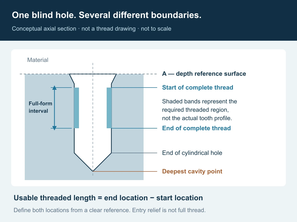
From an incomplete sketch to an agreed part definition. If these boundaries are missing from your files, HC Precision can help prepare drawings using the geometry and functional requirements you provide. Send the mating screw details and an assembly sketch as well as the part model. Drawing assistance can make the agreed depth references, protected surfaces and open decisions explicit, giving you a clearer basis for quotation and manufacturing approval.
Why a deeper tap movement is not the same as more usable thread
The leading portion of a tap has a chamfer that progressively generates the thread. OSG explains that its axial length depends on pitch and the number of chamfer threads, and must be considered when calculating the travel needed for an effective thread length.[1] The tap tip reaching a coordinate therefore does not mean that a complete thread has been produced to that coordinate.
Do not confuse the tap’s chamfer with the entrance chamfer on the part. One is tool geometry; the other is part geometry. Both can affect the space available, but they are not interchangeable allowances.
For a constrained blind hole, ask the supplier to review the actual tool lead, bottom geometry, chip clearance and approach/reversal requirements. A short-lead tool may reduce the necessary runout space, but “bottoming tap” should not be interpreted as permission to run into the hole bottom or as a promise of zero incomplete thread.
A thread-milling proposal may change the access and bottom-space calculation. It still needs a specific tool and geometry review. The purchaser should specify the functional result and protected material boundaries; the supplier should explain whether the proposed route can meet them. Avoid imposing a generic “add two pitches” rule as though it covered every tool, material and hole.
Check minimum engagement and maximum penetration separately
A joint can fail in either direction: too little thread is engaged, or the screw reaches an internal obstruction before the intended seating condition. A tightening torque reading alone does not distinguish intended joint clamping from resistance caused by unwanted contact, damaged threads or contamination.
For a conventional screw whose length is measured from its under-head bearing face, a useful first calculation is:
Screw penetration = under-head screw length − seated grip stack
The grip stack includes the relevant mating-part thicknesses and washers between the screw’s bearing face and the receiving-part entry surface. Use the actual seated dimensions; compressible elements, counterbores and unusual head forms need their own geometry. A countersunk screw’s catalog length, for example, must not automatically be treated as under-head length.
- At minimum penetration: check the overlap of complete internal and external threads. Account for the screw tip, its incomplete threads, any unthreaded shank, and the part’s entrance relief.
- At maximum penetration: check that the screw can seat with the required clearance from the actual internal profile. A deeper drill point does not necessarily provide clearance for the screw’s full tip diameter.
The required engagement is a joint-design decision, not simply a machining preference. NASA’s Fastener Design Manual discusses tapped-hole pullout in relation to engagement and the strength of the receiving material.[2] A fixed multiple of screw diameter is not a substitute for checking the materials, fastener and loading of the actual joint. This article does not establish a safe engagement length or tightening torque.
Worked example: nominally acceptable, but outside the insertion limit
Consider a hypothetical flat-bearing-head screw and rigid seated stack. Assume the design owner has already established 12.0 mm as the maximum permitted screw penetration, including the clearance needed for this particular internal profile. That limit is an input—not something inferred from the drill depth.
| Input or result | Calculation | Value |
|---|---|---|
| Under-head screw length | 20.0 ± 0.1 mm | 19.9 to 20.1 mm |
| Seated grip stack | 8.0 ± 0.2 mm | 7.8 to 8.2 mm |
| Nominal penetration | 20.0 − 8.0 | 12.0 mm |
| Minimum penetration | 19.9 − 8.2 | 11.7 mm |
| Maximum penetration | 20.1 − 7.8 | 12.3 mm |
The nominal assembly meets the stated ceiling exactly, yet the worst-case stack exceeds it by 0.3 mm. The design is not cleared merely because one sample screw seats. This calculation establishes a violation of the agreed insertion limit; it does not establish the exact point of physical bottom contact.

Possible corrections include a different screw length, a changed grip stack or an approved internal-geometry change. Each must be checked in both directions. Shortening the screw reduces maximum penetration but also reduces minimum engagement. Increasing hole depth may preserve engagement yet conflict with the remaining wall. Do not approve either change from this calculation alone.
Protect the material below and beside the hole
If breakthrough is prohibited, identify the protected boundary. For a simple flat-bottomed part, the relevant axial wall calculation uses the local material thickness and the deepest cavity point, including their limits—not merely the full-diameter bore depth. A drill cone can extend beyond the cylindrical portion.
For angled holes, nearby pockets, cooling passages or intersecting features, the shortest ligament may be elsewhere. Review a section or the actual 3D geometry rather than subtracting two dimensions that do not share a direction or reference.
State the maximum permitted cavity envelope or minimum remaining material where the function requires it. Ask the supplier to flag a conflict between the usable-thread requirement and that boundary before machining. A deeper hole, a breakthrough or a thread repair is a design deviation to review—not an automatic shop-floor solution.
What makes two thread-machining quotations different?
Thread designation alone does not define the work. Restricted bottom space, material condition, a difficult entry, treatment sequence and a documented depth check can change the process and inspection scope.
Sandvik Coromant’s tapping guidance connects successful threading with tool and drill selection, stable clamping and appropriate cutting-fluid delivery; coolant supply also affects chip evacuation and thread quality.[3] The tool and machining route should be confirmed for the part, rather than assumed from a general guide.
Ask bidders to identify the requirement driving an additional operation. Is it the last portion of complete thread, the no-breakthrough boundary, access to the hole, final-condition inspection or a dedicated gauge? Compare that scope before comparing the unit price. No fixed percentage captures the cost of all blind threaded holes.
If heat treatment or surface treatment is involved, define the condition in which the thread must be accepted. A pre-treatment check is not automatically evidence of final-condition fit. Record any permitted masking or finishing sequence rather than leaving it implicit.
HC Precision can coordinate material sourcing, CNC machining, EDM or wire EDM, grinding and inspection according to the complete part’s requirements. The route is selected for the geometry and material; not every component needs every process. Treatment timing and any external operations belong in the agreed scope.
The advantage is coordination around the finished part. A threaded feature must work with the component’s locating faces and mating geometry. Bringing those requirements into one process review helps keep the thread, adjacent features and acceptance criteria connected instead of treating each operation as a separate purchasing decision.
Match each acceptance question to its own check
A thread plug gauge and a depth instrument answer different questions unless the gauging system is specifically designed to combine them. Define the thread standard and class, gauge identification, depth reference and required inspection extent.
Vermont Gage describes how counterbores, reference surfaces and gauge-end geometry can affect depth readings. Its threaded-hole example shows why a depth indication must account for the relationship between the counterbore and the thread.[4] The practical lesson is to agree what the indication represents before treating it as proof of usable thread.
| Acceptance question | Evidence to agree | Important limitation |
|---|---|---|
| Does the thread meet its specified limit? | Appropriate calibrated thread gauging under the agreed standard and procedure | Do not invent a universal NO-GO turn count for every thread system |
| Is the required threaded region present? | A suitable depth-indicating thread gauge or another validated method tied to the specified reference | Gauge lead and end geometry must not make the indication misleading |
| Is the protected cavity boundary respected? | A suitable depth or geometry check; in-process evidence where final access is inadequate | Identify whether the result concerns the cylindrical depth or the deepest point |
| Will the specified joint assemble? | A defined assembly check plus review of screw and grip-stack limits | One sample assembly does not cover all tolerance combinations or prove joint strength |
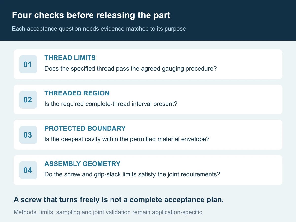
Keep the hole location, orientation, entry edge condition and cleanliness requirements in the plan when they matter to function. Record which holes and parts were checked. Do not force a gauge or screw through resistance and then count the result as an inspection pass.
HC Precision’s inspection resources include CMM, vision measurement and profile projectors for applicable dimensional and geometric checks. Thread limits and depth still require a suitable gauging method agreed for the feature. Tell us which results need documenting so the inspection and reporting scope can be included in your quotation, rather than left to receiving inspection.
A supplier-ready blind-thread RFQ checklist
Send the controlled model or drawing together with the mating screw information. The following questions make a useful review agenda:
- What are the thread system, nominal size, pitch, tolerance class, quantity and feature locations?
- From which surface are depths measured, and where must the complete threaded region begin and end?
- What entry chamfer, counterbore or spotface is required, and how does it affect engagement?
- What screw, length range and seated grip stack will be used? What minimum engagement and maximum penetration must the design meet?
- What cavity depth or remaining-wall boundary must not be exceeded? Is breakthrough prohibited?
- What material, condition and treatments apply, and at what stage must the thread satisfy acceptance?
- How will thread limits, threaded depth and any protected boundary be checked? Is inspection sampled or applied to every specified hole?
- Which unresolved items require customer approval before production, and are repairs or inserts prohibited unless separately approved?
These are inputs for an agreed drawing and acceptance plan, not a replacement for a complete engineering specification. If a value is unknown, label it as an open item; do not turn a supplier’s preliminary machining assumption into an unreviewed design requirement.
Frequently asked questions
Can I just specify a deeper hole to be safe?
Not without checking the protected material and neighboring features. More cavity depth may help the manufacturing route, but it does not select a safe screw engagement or guarantee that the required complete thread is present.
Does a GO gauge entering the hole prove sufficient thread depth?
Not merely because it starts or turns freely. The required depth, reference surface and gauge geometry must be part of the check. Use the acceptance procedure for the applicable thread system and a suitable depth indication where needed.
Can HC Precision help if the thread details are incomplete?
Yes. HC Precision can manufacture to customer drawings and help prepare drawings. You do not need to finish every drawing detail before making an inquiry. Send what you have, including the mating screw and assembly requirements, and identify what needs clarification. Agree the drawing-support scope and approve the completed requirements before machining; joint-strength decisions and any specialist validation must remain explicitly assigned.
Discuss your precision part with HC Precision
Explore HC Precision’s drawing-specific precision components, then send your part files, material condition, quantity and required date. Highlight the blind threaded features and mating hardware. With a released drawing, request a manufacturing quotation; with an unfinished model or sketch, request drawing assistance and a review of the unresolved requirements.
Bring us the part requirement—not just a thread size. Connecting drawing support, the manufacturing route and agreed inspection gives your project a clearer path from the initial inquiry to a defined finished component.
References and scope
- OSG — What is the chamfer? Primary tooling guidance on tap chamfer length and effective thread length; not a universal allowance for every blind hole. ↩
- NASA RP-1228 — Fastener Design Manual Historical engineering reference (1990), printed page 21, “Calculating Pullout Load for Threaded Hole.” Cited for the relationship between material strength and engagement, not as a current project certification standard. ↩
- Sandvik Coromant — Tapping operation tips Primary guidance on application, setup and coolant considerations; no equipment ownership or process guarantee is implied. ↩
- Vermont Gage — Depth Measurement Challenges Gauge-manufacturer discussion of depth references, counterbores and gauge geometry. The inspection plan must be selected for the actual part. ↩
Sources checked October 24, 2026. The numerical example and diagrams are original explanatory aids, not customer records, standard drawing symbols or manufacturing instructions. Final dimensions, joint adequacy, process feasibility and acceptance methods require project-specific review.