For a precision machined part, deburring is complete only when unwanted material has been removed without taking away material the part needs. A smooth-looking edge can still be wrong if it reduces a locating surface, changes a seal lead-in or removes part of a required thread.
The purchasing problem is not simply whether the supplier offers deburring. It is whether the drawing and inspection plan distinguish three things: remaining burrs, permitted edge geometry and loose contamination. Passing one check does not automatically satisfy the other two.
Deburring, edge breaking and chamfering are not the same requirement
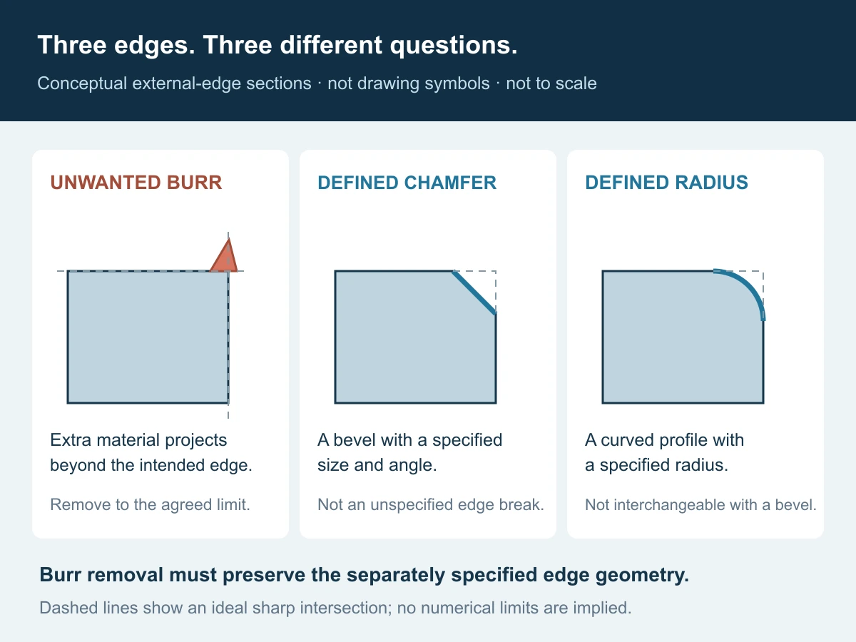
In this guide, deburring means removing unwanted material left at an edge by manufacturing. An edge break permits a controlled departure from a nominally sharp intersection. A chamfer is a specified bevel, while a radius requires a curved profile. These shop terms are not sufficiently precise by themselves to settle every drawing interpretation.
“Deburr all edges” does not automatically authorize a particular chamfer. Likewise, a finished chamfer does not prove that its own boundaries are free of residual burrs. A part can have the intended bevel and still require additional edge inspection.
ISO 13715:2017 addresses the indication and dimensioning of edges of undefined shape. Its public scope distinguishes these from geometrically defined edges, such as a specified size and angle, which use the general dimensioning principles of ISO 129-1.[1] The practical choice is to decide whether the function needs a particular shape or only a bounded edge condition. Use the agreed drawing standard to express that choice; do not invent a universal edge-break value.
Map the edge to its function before choosing the treatment
Start with the edges whose alteration could change assembly or service. Mark them on a drawing or annotated model so that a general finishing instruction cannot silently override a specific requirement.
| Edge or interface | What can go wrong | What to define |
|---|---|---|
| Bore entrance or locating shoulder | A larger edge break reduces the available cylindrical or seating contact | Permitted lead-in and the working surface that must remain |
| Seal assembly path | A projection or unsuitable transition can damage the seal during insertion | Lead-in geometry and surface condition appropriate to the actual seal and assembly |
| Thread entrance or exit | Uncontrolled finishing alters the entry or removes required full-profile thread | Entry geometry, required usable thread length and applicable thread inspection |
| Intersecting internal passages | An inaccessible projection remains even though both visible entrances look clean | The particular intersection, access and inspection coverage |
| Cutting, scraping or other intentionally sharp edge | Blanket rounding changes the function | The intended edge condition and an explicit exception to general edge breaking |
An exception to edge breaking is not permission to leave an uncontrolled burr. It means that burr removal must preserve the separately specified functional geometry. Conversely, a noncritical handling edge need not receive the same tightly controlled profile as a sealing interface.
Worked example: a larger hole mouth does not mean a larger working bore
Consider a hypothetical straight bore with diameter D = 10.00 mm and an entrance chamfer with c = 0.20 mm at 45°. Here, c is the radial and axial leg length—not the length measured along the sloping face. For ideal geometry, ignoring tolerances and corner blending:
The straight cylindrical portion remains nominally 10.00 mm. The chamfer occupies 0.20 mm of axial depth at that entrance, so the full-diameter cylindrical land begins below it. These numbers illustrate geometry only; they are not a recommended fit, tolerance or HC Precision machining capability.
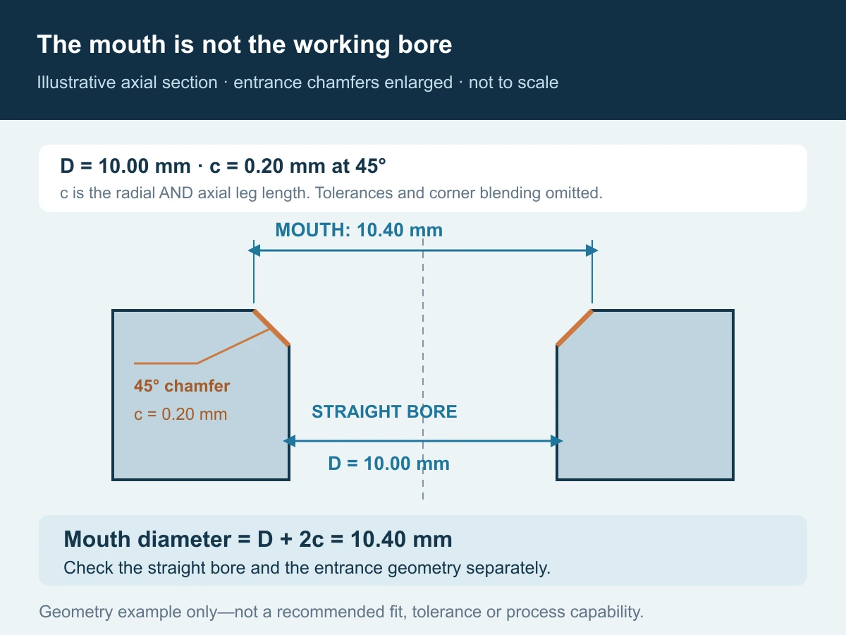
This creates two separate inspection questions: is the working bore correct, and is the entrance geometry correct? Measuring only the mouth cannot establish the cylindrical bore size. Checking the bore farther inside cannot establish that the chamfer is acceptable.
The same distinction matters when a short locating pin or sleeve depends on contact close to the entrance. Increasing the chamfer may make initial insertion easier while reducing the available locating length. That is a design change to review—not an automatic improvement in workmanship.
Inspect the edges you cannot see from the outside
A clean external outline is weak evidence for a part with cross-drilled holes, recesses or internal threads. The drawing review should identify each critical internal intersection, not simply label the whole part “burr-free.”
HEULE’s X-BORES range separates solutions for different intersecting-bore configurations and identifies some as customer-specific developments.[2] This supports an important process-planning point: the existence of a deburring tool does not establish that it can reach and control every intersection in a particular component.
Ask how the proposed method reaches the burr base, which adjacent surfaces it can touch, and how the result will be observed. A camera image should identify the feature and viewing direction. If part of the circumference is obscured, record the coverage gap instead of presenting the image as proof of the entire edge.
Threads need similar care. Sandvik Coromant discusses burrs at thread starts and, for certain thread-turning situations, at thread crests; it also notes the importance of deburring-tool positioning relative to the thread.[3] That is a reason to review the particular thread and process—not to apply one cutter path to all threaded parts. A thread gauge checks specified thread characteristics under its applicable procedure; it is not a substitute for examining every relevant edge or checking loose particles.
Select a process by where it removes material
“Machine-deburred” and “hand-deburred” describe routes, not acceptance results. A controlled manual operation may be suitable for an accessible feature; an automated route may offer useful repeatability. Either still needs an approved result and an appropriate check.
For each critical area, ask the supplier to explain:
- Reach: Can the operation access the actual edge, including the far side or internal intersection?
- Selectivity: What prevents it from rounding a neighboring seating face, enlarging an opening or altering a thin feature?
- Sequence: Which operation creates the final edge? Could a later cut, finish or rework create another burr or change the accepted condition?
- Consistency: What setup, tool-condition or operator checks keep the result within the agreed limits?
- Clean-up: How are detached material and processing residues removed before final acceptance and protection?
For a process that acts on many surfaces at once, establish which surfaces may change and how critical ones will be protected or rechecked. Do not choose it solely because it makes the part feel uniformly smooth. The supplier should confirm the actual route and feasibility; this guide does not imply that HC Precision offers every specialist deburring technology.
What should the drawing or purchase specification say?
A useful edge requirement answers five questions. It can be concise, but the answers should not depend on the person doing the finishing guessing the designer’s intent.
- Where? Identify the edge or edge group, including internal locations and exceptions.
- What may remain? Define the permitted residual edge condition, including burr limits where function requires them.
- What may be removed? Specify the permitted edge break or defined chamfer/radius, with the required limits and units.
- What must be preserved? Protect required land widths, usable thread, contact surfaces and functional sharp edges.
- How and when is it checked? State the inspection method, coverage and final part condition where these affect acceptance.
“Break all sharp edges” leaves the amount and shape of removal unresolved. “No burrs visible at the agreed magnification” is more reproducible, but it is still a detection condition—not proof of an absolute absence of material at every scale. If residual size matters, define the characteristic and a method capable of evaluating it.
Do not copy a generic numerical edge note from another drawing without checking scale and function. A permissible treatment on a large bracket may remove too much of a small locating or sealing feature. Where requirements are missing, label the supplier’s proposal as a proposal and approve it before the affected finishing work.
Define the edge while the part is still being planned. HC Precision makes drawing-specific precision components and can help prepare the drawing as well as manufacture the part. For a locating bore, sealing face or narrow slot, that means discussing the edge treatment alongside the CNC, EDM or grinding route. The useful outcome is an approved definition of what may be removed and what must remain, so the finishing operation supports the intended fit.
Keep three acceptance checks separate
| Question | Possible evidence, subject to feasibility | What it does not establish alone |
|---|---|---|
| Is an unacceptable burr still attached? | A defined visual or optical examination of the identified edge; a suitable internal view where needed | All inaccessible areas are acceptable, or the edge geometry is within limits |
| Was too much material removed? | Measurement of the specified chamfer, radius, land or adjacent functional feature using a suitable method | No loose particles remain in the part |
| Is the part sufficiently clean for its use? | An agreed cleanliness check appropriate to the component, contamination risk and specified limits | Every attached burr is absent or every dimension is correct |
A satisfactory roughness reading on a neighboring surface does not describe the entire edge. A dimensional report covering the main bore does not prove the condition of an unmeasured intersection. Ask for evidence tied to the particular acceptance question, rather than more pages of unrelated measurements.
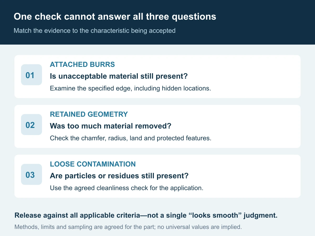
For an inspection plan, record the feature ID, criterion, method, viewing or measurement conditions, inspection extent and result. Define magnification or lighting when they affect a visual decision. A photograph used for dimensional judgment needs an appropriate scale and calibrated method; magnification alone is not a measurement system.
Agree whether inspection is sampled or applied to every specified feature on every part. One satisfactory first article establishes the condition of that article under the recorded checks; it does not establish every later part. Additional rework that affects an accepted edge should trigger the relevant reinspection and clean-up.
Compare the edge scope behind the quoted price
Two suppliers can quote the same model but different finishing work. One may include accessible external edges; another may include internal intersections and documented inspection. Compare those boundaries before treating the price difference as a difference in machining efficiency.
Ask each supplier to identify included locations, proposed edge conditions, specialist operations if needed, inspection extent and any separate cleanliness requirement. Keep drawing-review work, setup or dedicated tooling, recurring processing and inspection costs distinguishable where they materially affect the comparison. There is no universal percentage that deburring should add to a part price.
The useful cost question is: which requirement creates the extra operation, and what acceptance evidence does that operation support? Tightening every edge equally can create work with little functional benefit; leaving a critical hidden edge undefined can move the cost into assembly rejection or rework.
Frequently asked questions
Does “burr-free” mean every edge must be rounded?
No. An intentionally sharp functional edge can require burr removal while retaining its specified geometry. Identify it as an exception to general edge breaking and define how it will be accepted.
Is a general deburring note ever sufficient?
It can be useful where both parties share an appropriate workmanship requirement and no special edge condition is needed. Critical fits, internal intersections or controlled lead-ins require enough additional definition to avoid an ambiguous acceptance decision.
Can a gauge that passes prove the part is properly deburred?
Not by itself. A gauge checks the characteristics and engagement covered by its design and procedure. It does not necessarily assess nearby edge removal, hidden burrs or cleanliness.
Can HC Precision help if the drawing does not define the edges?
HC Precision can manufacture to customer drawings and help customers prepare drawings. Share the mating relationships and functional concerns so edge requirements can be reviewed. Proposed geometry, processing and inspection scope should be confirmed for the specific part.
Send a request that protects the functional edges
Bring the functional-edge question into your quotation. For HC Precision’s custom precision components, send the available drawing or model, material, quantity and mating information. Identify edges that locate, seal, guide or cut. If those requirements are missing, ask for drawing support; if the drawing is released, request manufacture and inspection to that revision. We can review the processing and inspection scope together, including access to hidden edges, before the order is finalized.
Please review the marked functional edges and internal intersections. Identify any missing edge limits, the proposed deburring scope, surfaces that must remain unchanged, and the inspection evidence included in the quote. Submit unresolved edge requirements for approval before processing the affected features.
The aim is not the smoothest possible edge. It is the correct edge, with the working geometry preserved and the acceptance evidence agreed.
References and scope
- ISO 13715:2017 — Edges of undefined shape. Official public scope; it distinguishes undefined edge conditions from defined geometry. Consult the agreed standard for drawing notation and detailed rules. ↩
- HEULE — X-BORES. Manufacturer information illustrating application-specific solutions for intersecting bores. It is not evidence of HC Precision equipment ownership or a guarantee for any proposed part. ↩
- Sandvik Coromant — Thread turning application tips. The deburring sections describe thread-start and thread-crest considerations in the stated machining context; their tool instructions are not universal process settings. ↩
The worked example and illustrations are explanatory, not customer case records or manufacturing instructions. Dimensions, methods and acceptance limits require project-specific agreement. Sources checked on October 17, 2026.