You can start a custom precision parts inquiry before you have a complete manufacturing drawing. Send the model, sketch or other information you already have, explain what the part must do, and identify what is still undecided. The next step is to agree what needs to be defined—not to fill the gaps with unverified dimensions.
HC Precision manufactures to customer drawings and can also help customers prepare drawings. This guide explains how to use that support: what to send first, which questions need engineering decisions, and what should be approved before machining starts.
An initial inquiry can contain open questions. A production release needs an agreed definition of the part, its critical requirements and how it will be accepted. These are different stages of the same project.
What can you send if the drawing is incomplete?
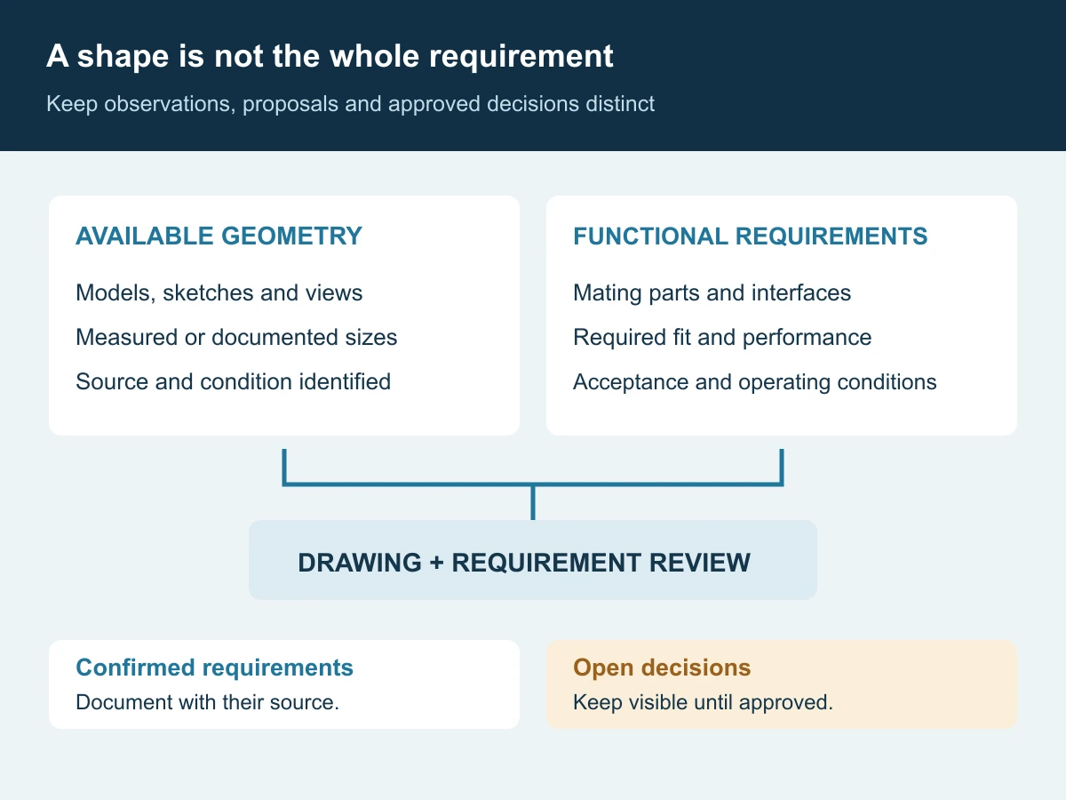
You do not need to redraw everything before making contact. Organize the available information so the supplier can distinguish documented requirements, observations and assumptions.
| What you have | What it can help explain | What still needs checking |
|---|---|---|
| A 3D CAD model | Overall geometry, feature access and possible machining routes | Whether tolerances, material, threads, finish and other requirements are included and readable |
| A sketch or marked-up PDF | Key dimensions, intended changes and which surfaces matter | Missing views, hidden geometry, units, ambiguous dimensions and the authority of each note |
| Photographs | Part identity, visible features and assembly context | Reliable dimensions, internal features, material condition and functional limits |
| An existing part or sample information | Accessible geometry and the condition of the available example | Whether wear or modification has changed it, and whether measurement or further investigation is feasible |
| A mating component or assembly view | How the new part seats, locates, moves or connects | Required fit, loads, permitted movement and the boundaries of the supplier’s scope |
Label each dimension by its source: existing drawing, measured sample, design target or preliminary estimate. Keep “unknown” visible where information is missing. A rounded dimension copied from a photograph should not quietly become a manufacturing requirement.
Before sending proprietary files or samples, confirm that you are authorized to share them and arrange the required confidentiality terms. Share what is needed for the review without exposing unrelated customer or project information.
The important gap is often design intent, not geometry
There are two different kinds of missing information:
- Information that may be established by inspection: an accessible outside dimension, a hole’s measured location or the observed condition of a surface.
- Information that requires a design decision: whether the hole locates a pin or clears a screw, what movement is acceptable, which surface establishes the assembly reference, or what load the part must withstand.
Measuring an existing hole does not establish its intended tolerance. Copying a worn sleeve does not establish its original running clearance. Identifying a part’s shape does not determine its material, heat treatment or required performance.
ASME describes geometric dimensioning and tolerancing as a way to communicate design intent, including form, fit, function and interchangeability.[1] For a drawing-assistance project, the practical implication is that someone must supply or approve the intended function. CAD work can document a decision; it cannot reliably recover an unstated one.
Tell the supplier what the feature does before asking how tightly it should be made. That gives the review a functional basis and helps avoid both unnecessary precision and insufficient control.
Six answers that make the first review productive
You do not need to solve every engineering question yourself. Start with these six answers and say plainly where help is needed.
- What does the part do? Explain its role and whether this is a new design, a replacement or a modification. For a replacement, describe the problem you want to solve rather than only requesting an identical appearance.
- What does it connect to? Identify mating parts and the surfaces that seat, locate, slide, seal or fasten. Include available assembly information.
- What conditions matter? State relevant load, movement, temperature, contact media or other known operating constraints. If these are not yet defined, flag them for review.
- Which requirements are already fixed? Separate mandatory dimensions, material and finish from features that can be discussed. Do not describe a proposed substitute as an approved material.
- What are you buying at this stage? Drawing assistance, a prototype, a replacement part or repeat production may require different deliverables. Include quantity and the date the parts are needed.
- Who will approve the result? Identify the person responsible for functional decisions and the checks that will establish acceptance.
This is more useful than sending an empty drawing template marked “all dimensions critical.” It allows the supplier to concentrate questions on the interfaces and decisions that could change feasibility, cost or the delivered result.
Agree what drawing assistance includes
“Help us draw the part” can mean several jobs: documenting an existing approved design, completing missing manufacturing information, measuring an available component, or developing new functional geometry. Those scopes are not interchangeable.
Before drawing work begins, agree the following:
- Inputs and open questions: which information the customer provides, what the supplier will review, and what cannot yet be confirmed.
- Deliverables: whether the work includes a 2D drawing, a 3D model or both, and which file formats will be supplied.
- Decision responsibility: who proposes technical choices and who approves the functional requirements. Drawing assistance should not be assumed to include full product development or application validation.
- Commercial terms: included or separate drawing charges, revision scope, review milestones and arrangements for later changes.
- Release and file use: which approved revision will control production and what editable files, reuse permissions or ownership terms are included.
HC Precision’s drawing support can be discussed alongside the manufacturing requirement. Where sample measurement or broader engineering work is needed, confirm its feasibility and scope separately. Do not assume that every unknown can be resolved from a photograph or that every drawing task is included free of charge.
The value of drawing support is that the definition can be reviewed with manufacturing in mind. HC Precision’s component work includes custom inserts, cores, cavities, punches and other precision details. Bringing machining, EDM, grinding and inspection considerations into the drawing discussion helps expose an inaccessible feature or an unclear datum while it can still be resolved on the drawing. The customer approves the functional requirements; the agreed production route then follows that definition.
Do you always need a 2D drawing as well as a 3D model?
No—not as a universal rule. ISO 16792:2021 supports both a 3D model-only method and a 3D model accompanied by a digital 2D drawing.[2] The important issue is whether the agreed dataset communicates the necessary product requirements and whether both parties can interpret it correctly.
A geometry-only model is different from a controlled model-based definition containing the required annotations and associated information. For many custom-part orders, a 2D drawing is a practical way to make critical tolerances, threads, material condition and finish explicit. Protolabs Network’s technical-drawing guidance likewise highlights critical features, threaded holes and special requirements that need communication beyond the basic shape.[3] That is manufacturing guidance, not a HC Precision file-format or tolerance guarantee.
Confirm the files, units, revisions and which information controls. If a model and drawing disagree, resolve the conflict before making the affected feature. Adding another file is useful only if it removes ambiguity rather than creating a second, inconsistent definition.
Example: the model shows a mounting block, but not how it locates
This is an illustrative review scenario, not a HC Precision customer case.
A customer supplies a model of a small mounting block with a central bore and four surrounding holes. The overall shape is clear. The intended assembly is not.
Before preparing the manufacturing definition, the review needs to establish whether the central bore supports a rotating shaft, locates a stationary sleeve or simply provides clearance. The surrounding holes might fasten the block, locate it, or perform different functions. The mounting surface and the relationship between that surface and the bore also need to be understood.
Those answers can change the necessary size, form and location controls, the material choice and the inspection approach. Applying the same tight tolerance to every feature does not resolve the missing information.
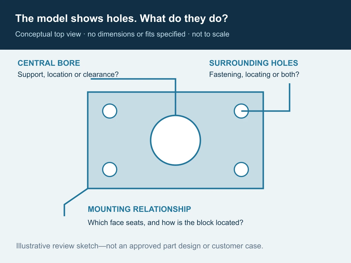
A useful review record has three columns: question, proposed resolution and approval status. For example, “What locates the block?” remains open until the customer confirms the assembly arrangement. A supplier’s proposal is valuable input, but it should remain visibly proposed until accepted by the responsible party.
The result is not simply a more detailed picture. It is a definition that connects the part’s geometry to the way it must work and be inspected.
Separate initial discussion, quotation and production release
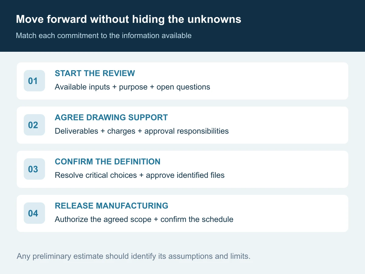
Incomplete information does not need to stop every activity. It does change what can responsibly be promised.
| Stage | Useful outcome | Boundary to keep clear |
|---|---|---|
| Initial review | Identify available inputs, likely work required and the questions blocking progress | A discussion of feasibility is not approval of an unspecified design |
| Preliminary estimate, if feasible | Provide a planning basis with stated assumptions and exclusions | Identify which unresolved choices can change price or timing |
| Confirmed scope and quotation | Agree deliverables, quantities, technical requirements and commercial terms | Specify any remaining hold points and the event that starts the lead time |
| Manufacturing release | Authorize work against identified, approved files and requirements | Close open items affecting the authorized work; do not silently convert assumptions into requirements |
A purchase order can include drawing-development work before the manufacturing definition is complete. It should distinguish that authorization from permission to machine the final part. If early material procurement or other limited work is requested, define exactly what is authorized and how subsequent changes will be handled.
Keep customer review time visible in the schedule. “Ten days” means little if one party starts counting at inquiry receipt and the other starts after drawing approval. No standard lead time should be inferred from this workflow.
A practical first message to send
Use the following structure to explain the project without pretending that the design is finished:
We need a custom precision part and would like help completing the manufacturing definition.
- Purpose and mating parts: explain how the part is used and attach available assembly information.
- Available files: list models, drawings, sketches, photographs or sample information and their revisions.
- Confirmed requirements: identify the dimensions, material, finish or other conditions that are already approved.
- Open questions: state what needs clarification or a supplier proposal.
- Order scope: give the quantity, required date and whether drawing assistance and manufacturing are both requested.
Please identify the missing inputs, proposed drawing deliverables, any separate charges and the approvals needed before production.
Use “not yet defined” where appropriate. A short, accurate inquiry is a better starting point than a complete-looking specification built from guesses.
Frequently asked questions
Can HC Precision help create a drawing, or only machine supplied drawings?
HC Precision can work to customer drawings and help customers prepare drawings. The required inputs, deliverables, charges and approval responsibilities should be agreed for the particular component.
Can I get a firm price from photographs alone?
Photographs can start a review, but they do not define all geometry, material and acceptance requirements. Whether an initial estimate is useful depends on the part and available information; label assumptions clearly before relying on it.
Can an existing sample replace a manufacturing specification?
Not automatically. A sample shows an observed condition, which may include wear or previous modification. Discuss measurement feasibility and distinguish measured geometry from the intended new-part requirements.
Who chooses the tolerances when the customer does not know them?
The supplier can discuss manufacturability and propose controls, but the choices need a functional basis and approval by the responsible designer or customer. Precision should be assigned to the features that require it, not chosen as a blanket promise.
Start with the information you have
Start with your part, not a perfect document package. For HC Precision’s custom precision component manufacturing, send the files you have, the component’s function, mating information, quantity and target date. Tell us whether you need manufacture to a released drawing or help developing one. We can discuss drawing deliverables and the machining and inspection scope in the same review, giving you a defined next step toward an approved manufacturing specification.
You do not need a finished drawing to begin the conversation. You do need an agreed requirement before the corresponding manufacturing work is released. That is how drawing assistance becomes a practical route to parts that can be quoted, made and accepted consistently.
References and scope
- ASME Y14.5 — Dimensioning and Tolerancing. Official overview of communicating design intent through dimensioning and tolerancing. The applicable standard and edition must be agreed for the project. ↩
- ISO 16792:2021 — Digital product definition data practices. The public scope identifies model-only and model-plus-drawing methods; it does not mean that every unannotated model is a complete specification. ↩
- Protolabs Network — How to prepare a technical drawing for CNC machining. Practical guidance on communicating critical features and manufacturing requirements. Its platform rules and numerical capability limits are not HC Precision specifications. ↩
The review framework, example and illustrations are editorial guidance, not measured customer results or a guarantee of design, tolerance, price or lead time. Drawing assistance and manufacturing scope are confirmed per project. Sources checked on October 15, 2026.